** The Marshall TSL122 JCM2000 Repair/Mods Page **
Photos/Text JC Maillet (c) 2007/2008/2009
 |
A little background check doesn't hurt, go to Harmony Central and read what players have to say about these amps
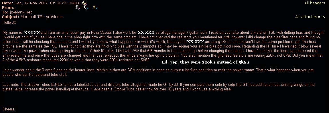
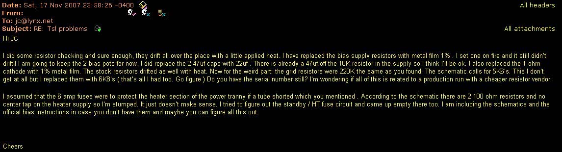
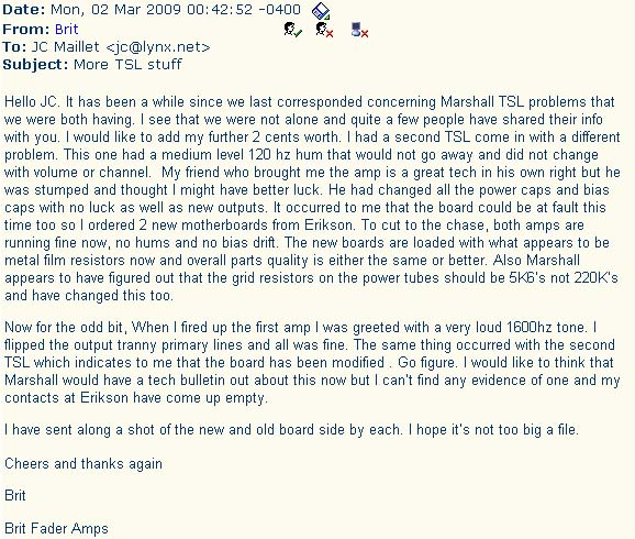
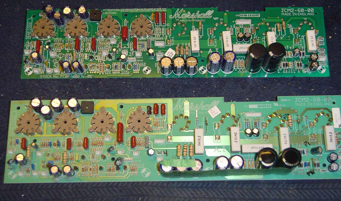
I've worked on a bunch of JCM2000's now and I've seen two sets of problems crop up. In this one TSL122 I'm about to describe the mother board was found to be populated with negative Temp-coefficient resistors. This sent the bias voltage for a loop when the amp got hot - I'm sure it must be an accident at the factory or something. In a DSL100 I didn't find that specific problem but in all JCM2000's so far (TSL's, DSL's) I've found 220k grid block resistors on the power tubes instead of the customary 5k6 as indicated in all schematics - converting them to stock values definitely makes an audible change !
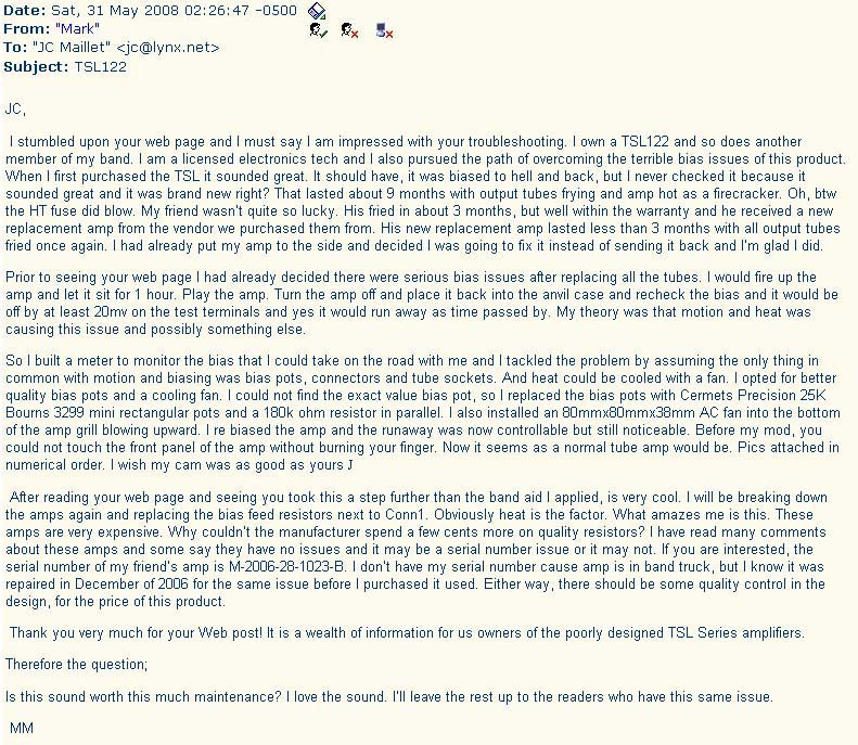
Hot Rat's Nest - The TSL122 Thermal Runaway Saga
This amplifier first came in with a pair of crisped-out power tubes on one side of its output stage and some nagging microphonic problem. Having never seen one of these before I assumed that the amp had no major design or manufacturing flaws and likely had faulty power tubes put in and/or the bias hadn't been adjusted properly previously ...
I biased in a new set of EL34's to around 35mA per tube (B+ just below 450vdc) ... found/fixed a cold solder around the B+ connector (W5 blue) on the mother-board ... rebiased, let the amp idle for a while as I normally do, double checked bias a few times more using the bias pins (which I usually don't use but at 1.3 ohms they give a conservative reading anyway) ... played the a bit more and sent the amp back to the owner ...
The amp resurfaced a week later with a pair of tubes fried on the other side of the output stage, and the HT fuse again did not blow - something I couldn't figure out. All this prompted a serious in-depth study of the overall design.
 |
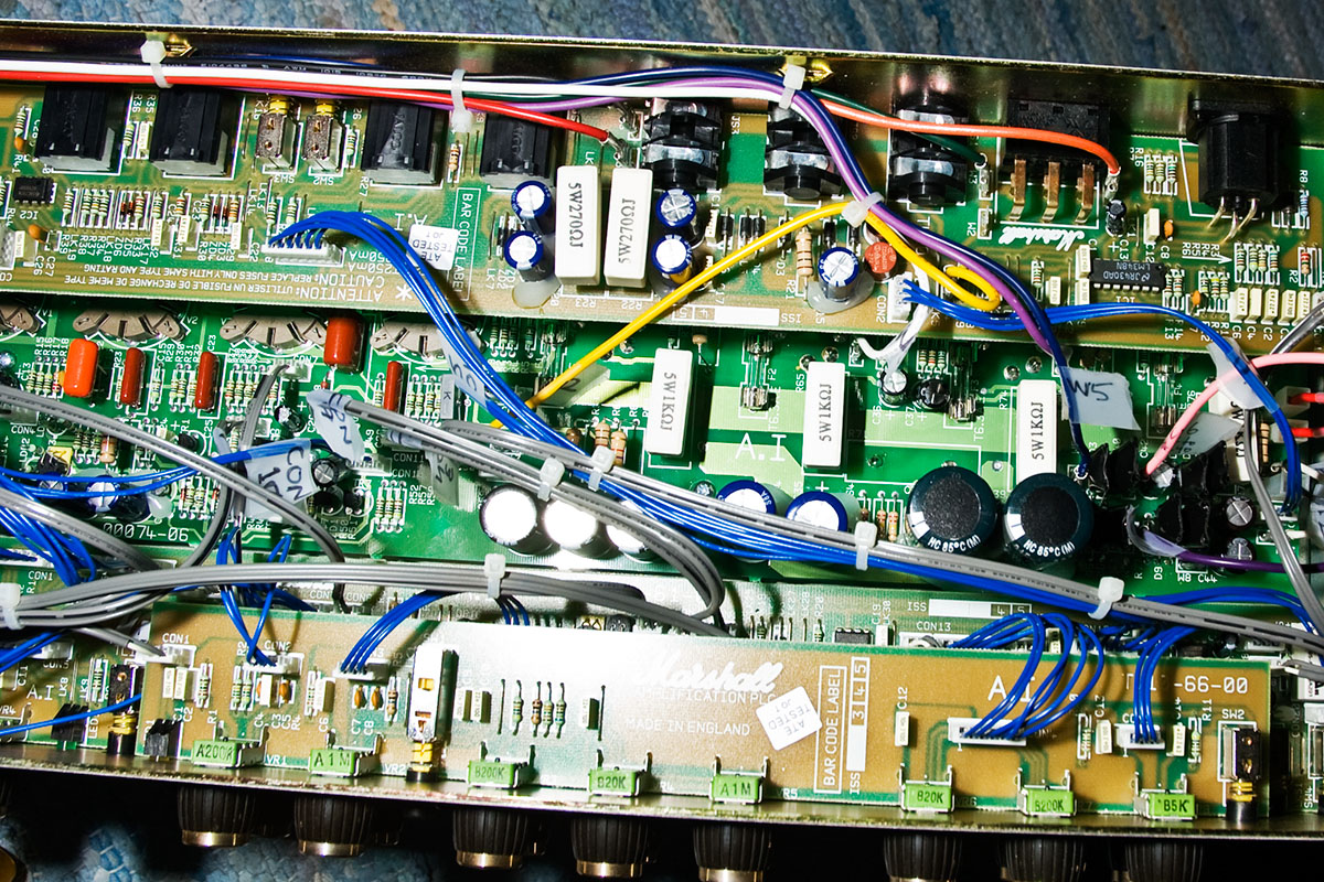
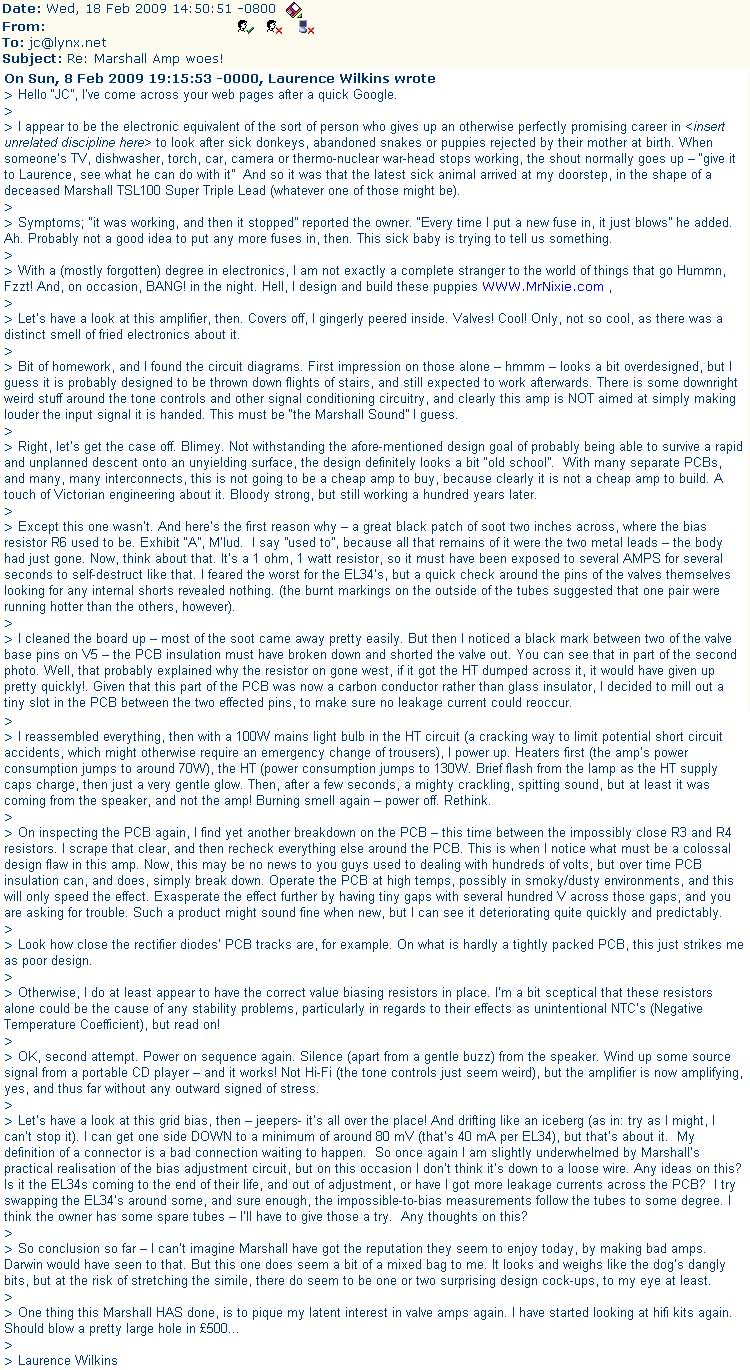
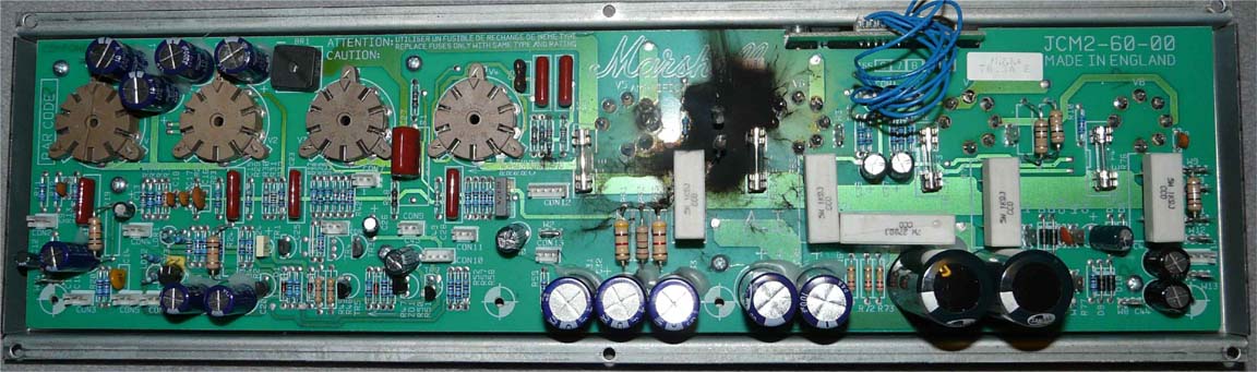
I began to notice strange things happening while the amp was idling - basically a form of runaway bias drift was taking place over the course of an hour or so, something I hadn't seen before. The mother-board showed severe temperature stress on all four power tube sockets which are directly mounted to the mother board - a potential source of untold and incurable problems on the one hand. Had the amp been under warranty I would have turned back at this point and had the customer send his amp back to the factory or ask for an exchange. But, that wasn't the case ... so trudging on ...
 |
The bias circuit was obviously a first place to look for leading clues in the mishaps. Being of the dual type (not a good idea to begin with) in which two trimpots mounted on an external board connected to the mother board via a multi-wire connector (another not-great idea) adjust bias on each pair/side of the output stage - this off-board arrangement invites lots of trouble. My original beef with general dual-biasing is outlined in my Tube Amp book (IF&MTA), but the beef I have with mutually interactive versions of that idea is way worse.
 |
Siding with reason and caution I decided to hard wire a standard/classic single 10k bias pot directly to the mother board (all other bias circuit component values remain the same). I went to single control because having two degrees of adustability made it difficult to isolate the source of "long term" bias drifting I was observing on the bench - basically I wasn't sure if grid current draw on one pair of power tubes was affecting the bias on the other side of the output stage. Installing it as such elliminates that 2-way variable and, more importantly, renders the bias circuit as a whole more immune to circuit "opens" via vibrationary action and faulty/intermittent connectors which I also had to rule out as a potentially likely possibility for frying tubes. Who knows about these connectors, I guess they're ok now that I've tugged at them while the amp is working with no apparent sign of weakness - still, the fact that the bias lines are going through two sets of connectors before making it to the main circuit is pretty balsy, almost contradictory to some other overkill safety features in the amp.
 |
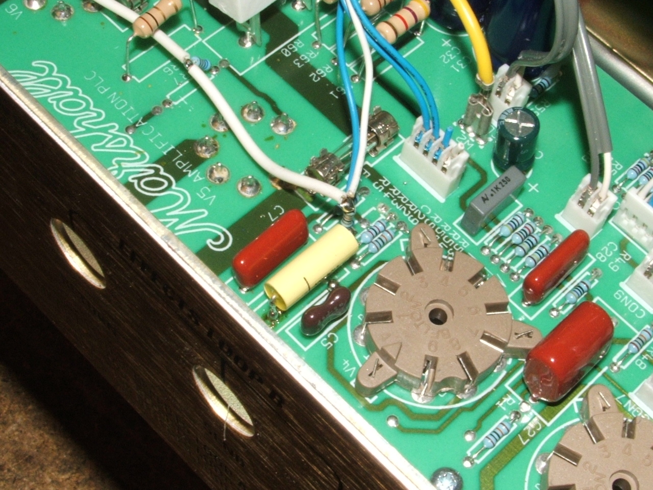
Scraping the enamel off the traces corresponding to pins 2 and 6 on the bias board connector and mounting a support connector to connect both traces together into a common bias feed to the power tubes. This doubles the total bias feed filter cap value to 100uF which lowers output stage hum at the expense of slightly longer charging times - not worth fussing over.
 |
The new bias pot (10k - 1/4watt) is mounted via two standoffs on pins 1 and 7 of the bias board connector. The old bias pots are removed from the board and only the bias measuring pins remain active in the circuit "just in case" they're needed in the future by someone. Or I'll remove the bias board altogether - I don't use the bias pins for biasing anyway. I reconnected everything together and was ready to do some more testing.
 |
 |
 |
one may wonder if the location for the new bias pot is optimal - personally I don't like the idea of snaking lines around in a high gain amplifier ... potential for added radiation-prone interference increases rapidly with distance ... so the safest thing is to instal the trimmer right over the connector, in effect shortening the wiring distances (always a good thing if anything) ... I'm not worried about heat too much here since the circuit is shielded by a metalplate and the board lies well below the tube sockets ... about access, a long-neck screw driver will do the trick ... but I agree it's a PITA to have the control on the opposite side to tranny access but that's how it is for now based on the other considerations mentioned before ... suggestions are welcomed
Note-book Diagram of my TSL-122 Bias Circuit Mod
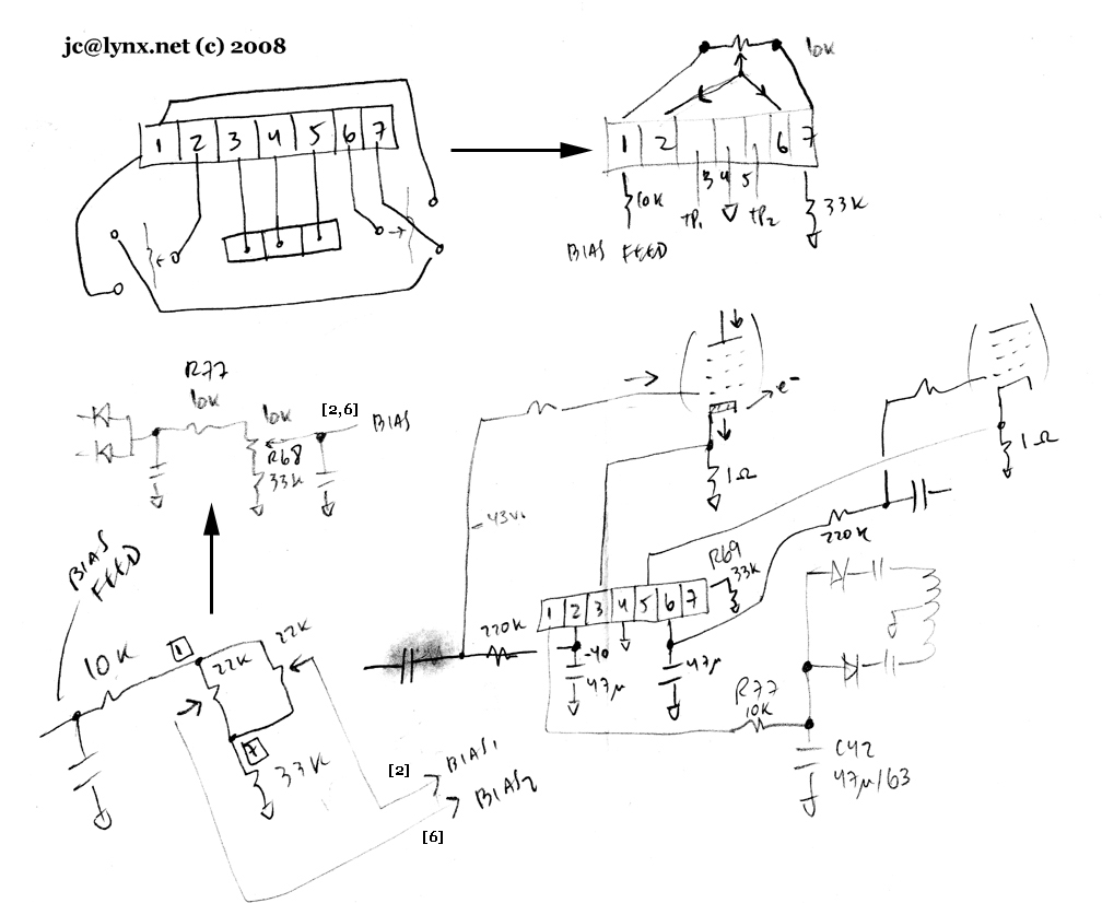 |
The following diagram was drawn by a buddy while I'm shouting out label tags at him from the other side of the bench ... I know it's ugly and shouldn't be posted but it's there just in case it might help someone who forgot to label their wires ... maybe someone will send in a better diagram for me to post.
 |
Wrong Value resistors + Thermally Weird Components on Motherboard
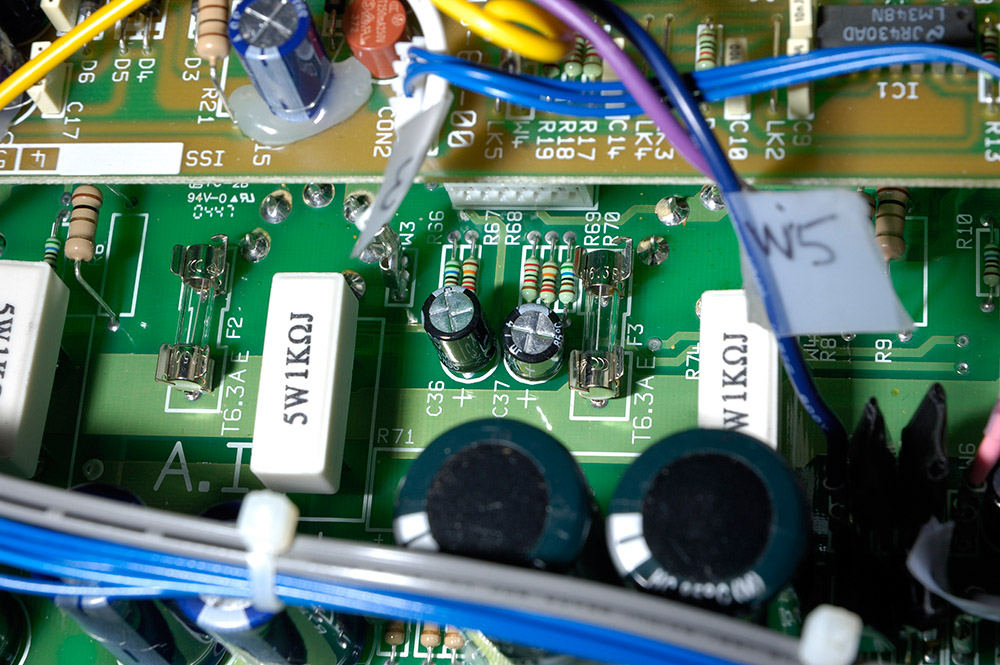
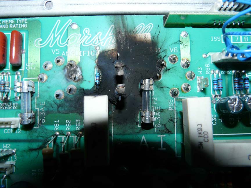
This is where the weirdness begins. Having gone back to the usual tranny-shunting for measuring plate currents I discovered that a matched quad of tubes would kreep to arbitrarily high currents over a period of an hour or more ... this occured regardless of initial bias setting and then a spread between sides would develop as the increase took place. Two things I noticed were of importance here, (i) if I swapped tubes the spread tendency remained the same socket-wise, pointing to the circuit and not the tubes, and (ii) if I turned off the amp once it was well warmed up and measured the bias feed resistor values I found that one measured around 110k instead of its nominal 220k and the other laid around 180k ... something funny going on (!)
 |
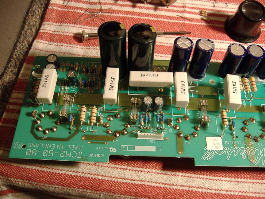
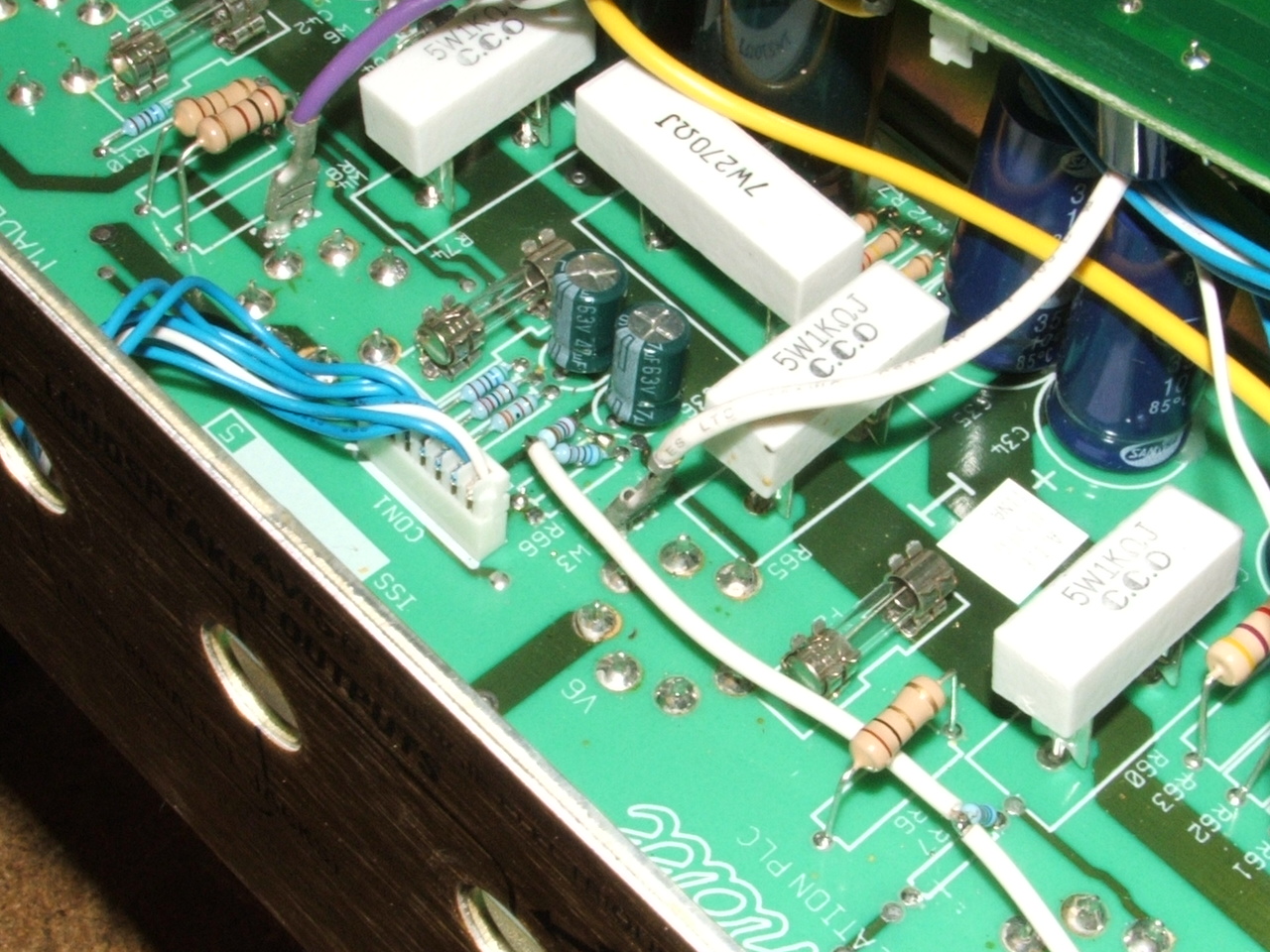
I pulled both resistors out and tested them under a blow-drier and sure enough both these critters dropped their values when heated. that's Negative TempCo shit. Could it be that all resistors on the mother-board had negative TempCo's ??? I wondered how they would affect the bias circuit, and other things not to mention ... To answer part of that question I replaced all resistors on the mother board that were part of the bias circuit (R68=33k, R77=10k, R67=220k, R69=220k) by 1watt film resistors - they hardly budge in value when placed over the flame of a lighter. This made a big difference - the tendency towards drifting was muchly slowed down and at some point it peaked to a semi-stable value unlike before. The only thing to exlain the residual bias drift and divergence towards a semi-stable value was the burnt sockets and oxidized contact with the mother-board. My advice here is to give the amp about an hour to settle following this mod to make 100% sure all is fine ... btw, as reference, I found the TSL122 sounded good with these GT-JJ's tubes biased quite colder than what I would mormally shoot for, namely around 54mA per side total by tranny shunt.
 |
The other thing I noticed was grid blockers (R7, R10, R66, R70) lying at 220k instead of the usual 5k6 ... this finally explained the choked clean sound and a muddy/grainy power distortion tone. By replacing them with 6k8's (closest I had) the classic Marshall sound came out more, it was slightly more alive and clearer in clean mode and the distortion tones were less grainy - to my ears anyway.
Scoping the High-Tension Circuit
One good thing about 1 ohm resistors in the cathode circuits is in giving the ability to scope the pentode plate currents indirectly through them. A 500mV peak cathode voltage swing translates into a total 500mA peak current sink per push-pull side, this justifies the standard use of a 1A fast-blo fuse in the B+ circuit of 100watt EL34 amps, right in series with the output transformer feed ... bring a scope to your gig and hook up :)~
 |
I think this mother board could have suffered damage from several previous harsh malfunctions around the power tube sockets and I guess it's only a matter of time to see if these corrections will allow the amp to hold up over time (unlikely I'm afraid - that's PCB based amps for ya). Not a job I could guarantee, so I warned the customer about it and he was ok about it.
 |
 |
 |
 |
DSL-100 check-up
This DSL100 mother board had 220k grid blockers, I piggy-back them with 6k8's as I did in the TSL122 ... and the bias circuit resistors were changed to 1% metal film ... yes, I'm just about to change that 10k bias circuit resistor in the back ... the bias resistors on this amp also exhibited NTC behavior which again was confirmed OFF-BOARD using a multimeter and 1200w hair drier ...
 |
 |
 |
 |
 |
Note: A few guys I talked with were thinking of drawing up replacement boards - for anyone nuts enough to tackle this re-design I would suggest doing a board with a cut-out around the power tube section and mount the power tube sockets to a metal bracket instead of the PCB board - I got an email from a dude who says he did it successfully ... the only resistors I think need changing are in the bias circuit and the grid-blockers - they should be 5k6 and not 220k ... all other resistors, incl. screen block power resistors, I wouldn't touch unless there's a reason ...
 |
 |
 |
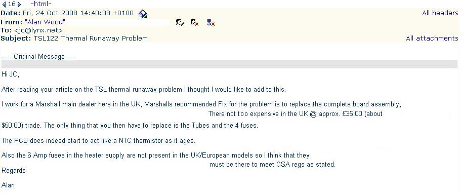
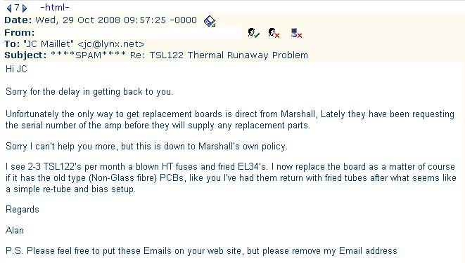
Much appreciated Alan !
More ...
 |
 |
 |
 |
 |
 |
 |
 |
 |
updates ... 07/09
 |
 |
 |
 |
 |
 |
\\\ CONCLUSION ///
I got in touch with the top dawg at JAM industries in Montreal and he had a few random ideas to offer: C46 the
small enigmatic ceramic cap next to the last power tube circuit is said to short out - of course, this wouldn't
explain bias drift at all for a shorting cap on the B+ line would drop tube current if anything and eventually blow a fuse (assuming fuse circuit would work here)... recommended advice on C46 is to snip or replace with 1500v ceramic cap (if you feel you must have a cap there) - why they put one in the first place is beyond me since the amp doesn't oscillate as far as I can see on a scope ... I tried the snip on the TSL122 I have here and it did nothing to fix bias drift ...
I'm not sure how much more I can quote here, but bad Russian tubes were said to be the cause of much malfunction in these amps // Winged "C" were recommended over Sovtek ... aside from mentioning the usual output jack connection issues that's typical of all gear nowadays, they said the mother boards shouldn't be replaced on these amps except if the mother board was fried badly ... (???) ... when I asked about bias drift issues it came up as "outside of C46 shorting out that doesn't happen" ... the price for a new mother board from JAM was around $168CDN ... [* if you do buy one please send in pictures and details *]
Marshall wouldn't get back to me on this so I can't answer anybody's questions with any degree of certainty - I can only echo whatever info you dudes are discovering ... at some point I will try to hook up the tubes remotely on this TSL122 since there are some reports of that fixing the problem - but we'll see ... it's not on my list of priorities to re-design this bird ... at this point, unless you're a DIY freak, the best option is to buy a new mother board or move on to another amp ... bottom line is you've got a double sided PCB board in a hot environment that has very tight tolerances - that's asking for trouble just by the very nature of the assembly, never mind NTC resistors showing up in the mix (which I'm sure was a mistake at the factory) ...
\\\ January 2011 ///
It's been a few years now since the replacement motherboard for these amps came out - the guys at JAM in Montreal will only sell you one if you tell them (insist even) that yours is badly fried and carbonized around a tube socket and "can't" be cleaned/repaired reliably ... save your sweat and avoid doing the mods I went through and get yourself a replacement board // the component values and quality on the new MB are vey high - it's obvious the guys at Marshall went to great lengths to do this one right (sure took long enough!)
From emails I've gotten over the years it seems like there is a brief period of time (late 90's) where the DSL/TSL amplifiers seem more suspect than in others years of production ... part of the problem is Marshall's fault // 220k grid blockers on the power tubes (as seen in some official schematics) is certainly a way of encouraging bias drift ... it seems the problem was later compounded in some units when someone at the factory accidentally (?) loaded the machines with neg Temp Co resistors in the bias circuit area (this has been confirmed by a few other people as well) ... stories about the PCB being conductive have been doubted by other reputable amp techs ... I'm also not sure that C46 was an issue either, tho Marshall certainly went to lengths (again) to put a high quality component in that spot.
Still, hard to say at this point if it's totally a case of a badly designed/built (era) amp, bad tubes or both. According to Eric barbour EL34's are prone to meltdown if the Screen winding is not aligned well enough to the Plate winding. JJ is one of the few tube companies that offers hand-aligned Screen windings on some of the production tubes (eg. KT66, KT77) ... otoh, none of the Russian made tubes (Sovtek and Winged-C) have this feature // sometimes I wonder if this explains the higher reliablity I've seen over time with JJ power tubes. My $0.02
 |
 |
Thanks for the latest update John !!
\\\ Summer 2011 ///
... peeps working hard at solving this problem even further (mucho XCLT!!!)
03/06/2011, John Rigg ...
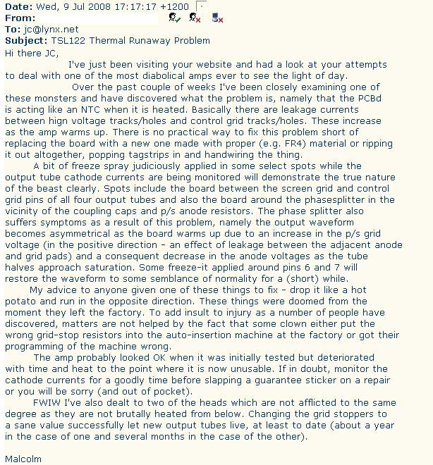
>> Hi JC,
>> I just stumbled on your TSL mods web page after struggling with a TSL122 belonging to one of my amp repair customers. After a fried set of new EL34s plus a lot of work replacing every component in and around the bias circuit, I reached the conclusion that the PCB insulation resistance was decreasing when it got hot.
>> If I'd seen your web page before I got this far I could have saved a lot of trouble and expense. I can confirm everything your correspondent Malcolm said about the PCB material. The main board looks like FR3, which is something I'd never use in high voltage high temperature applications. I suspect it absorbs moisture over time and then starts to lose its insulating properties when heated. This will depend on your local climate so YMMV.
>> BTW I have found that some TSLs produce RF oscillation if C46 is removed. I usually replace C46 with a 2kV ceramic disc as the 500V one does tend to short out.
>> Regards, John
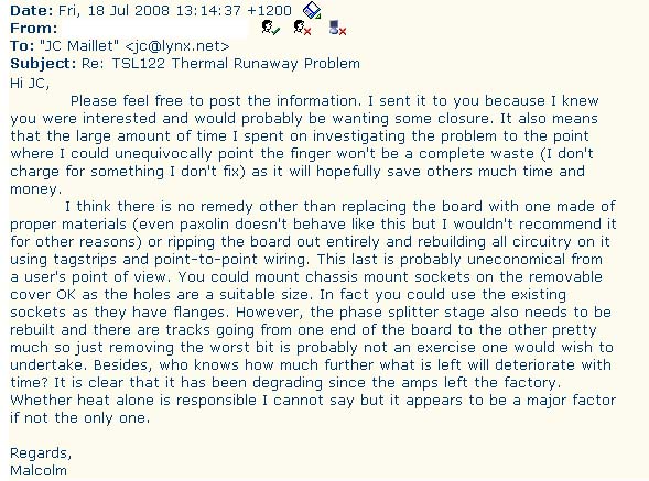
Hi JC,
Since I emailed you I've done some more testing. I pulled out V5 and isolated the control grid pin on the V5 valve base by removing R7. then hooked up a 500V insulation tester to the screen grid and contro grid pins on the valve base.
At room temperature the insulation resistance was off the scale of my tester at more than 4500 megohms. After a few seconds of heating with a hot air gun it dropped below 10 megohms, which would be enough to reduce the negative bias by several volts.
I think that's pretty conclusive evidence that the PCB is conducting
when it gets hot.
Regards, John
19/08/2011, John Chambers ...
Hello JC, my name is John Chambers (also JC) & I run Champ Electronics here in Nottingham, UK. www.chambonino.com You may have heard of me?
OK, like yourself & probably many engineers....I've had numerous Marshall JCM2000 TSL amps in for repair & especially with the drifting bias problems!
I have in the past spent a small amount of time chasing this drifting problem but usually end-up fitting a new board from Marshall.
I had another one in last week with yet again the same drifting bias problem. As you already know it always seems to be worse on the right-hand pair of tubes (as viewed from the back) with maybe just a little drift on the left pair. Having a little spare time I decided to nail this problem once and for-all........this I have now done & the mod is simple, cheap & reliable!
Finding the problem didn't take very long at all.....to my surprise! With both bias pots turned-up to full voltage & checking this to be correct on both caps C36 & C37.....this eliminated many things right away......including the bias pots, the cable connectors to-from them etc. Checking the voltages now after each of the 220k feed resistors (R67 & R69) did indeed confirm that the left side had dropped about 1 volt but the right side was about 10 volts down @ 36.3 (the amp was well hot at this point).
OK, knowing this has to be a temperature problem I proceeded to freeze various components along the bias chain. On spaying the block of 4 resistors (R2, R3, R4 & R5) the voltage immediately came right back up! The problem is so simple really. R4 is laying right next to R3 & R2 splitter plate resistors and these get warm. Whether or not the board becomes a little conductive here I am not sure but, when the next one comes in with the same problem again (as it surely will), I'm simple going to change the 82k & 100k splitter resistors for 2 watt type & mount them up in the air....well off the board & see what happens? Anyway, after I had done the mod she remained perfect for 10 hours test!
As you so rightly said....if an amp has 220k grid stops these need to go.....replaced with 5k6 as what they should be & this one had the correct 5k6's anyway.
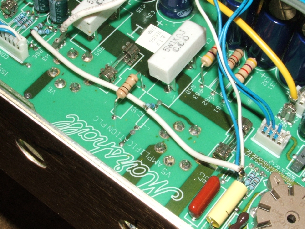
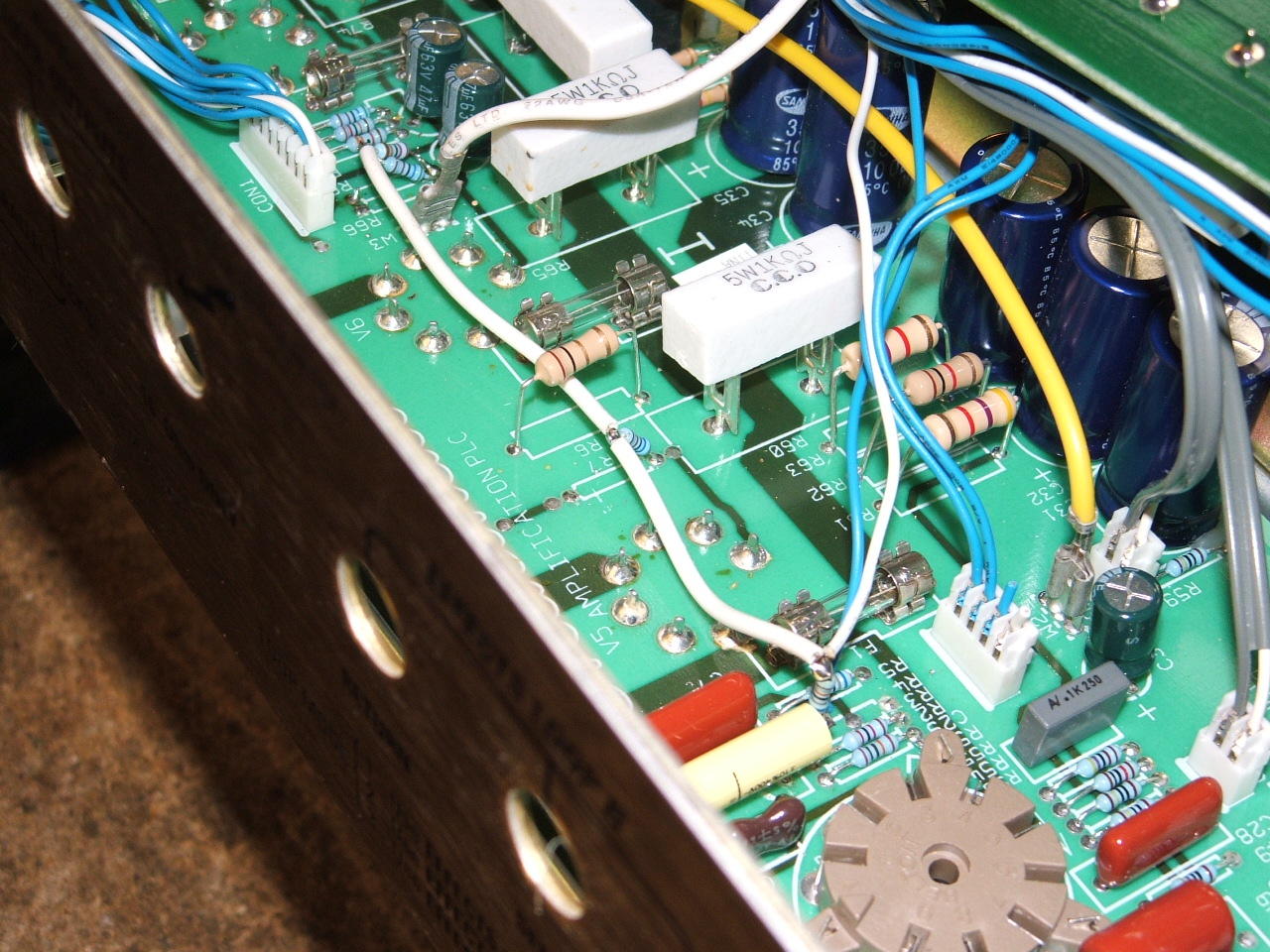
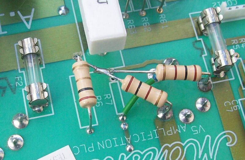
With this fault being so simple, All that needs doing is to remove the 680k (R4) resistor from the board completely.....along with lifting just one leg of each of the following. Output of cap C6, V5 grid-stop (R7), V4 grid-stop (R66) & the 220k bias feed resistor (R67). Simply then surface wire the components as in the attached photos. I glue-gunned them afterwards to make them secure. Problem completely gone!
There was still a slight drift of 1 volt on the left-hand pair but this is liveable with. The same thing could be done for the other pair if required?
Anyway JC, I hope this info is of help?
Kind regards, John.
 |
 |
 |
 |
 |
 |
04/09/2011, Brendan Donnelly ...
Hi JC,
I stumbled across your forum years ago, and since then I have developed a repair that seems to work quiet well.
I have repaired countless TSL100's and DSL 100's that suffer from the bias drift cook valve destruction problem.
As all your other emails state there are several issues.
Cutting to the chase, the repair that seems to work for me is. To remove all power tube sockets.
Drill out PIN 5 on the PCB (control grid) so it totally clears the PCB/pin of the tube socket when it is reinstalled.
Then point to point the complete bias/and coupling section with new resistors and correct values.
I usually start from the coupling caps from the driver tube, and keep totally free from the PCB.
There are many ways of mounting the components of the board, (tab mounts etc).
This mod ensures a clean path to the control grid and avoids the voltage drift problems.
I point to point with 1 watt resistors.
I have also had other failures due to tracking. Again you can follow the same idea.
(I had the heaters tracking on one repair, so again I point to point wired them)
In the worst case I believe I could cut the whole power tube section out of the PCB
and point to point the whole power section. But so far I have been lucky and have not had to do this.
I live in Australia and the price for a complete PCB was over $350 dollars. I have replaced
with new PCB's before for customers who have requested this, but many of them are
not so wealthy musicians, so the mod is a little cheaper for them.
I had to develop these mods as I was getting so many of these amps in for repair.
I have none come back as yet. So I believe that the fix seems to work.
hope this helps other techs. Thanks for the great forum
which helped me on the path to get things sorted.
regards, Brendan
\\\ update: Fall 2011 ///
Fred Skenderbeg's Solution ...
I recently did a search on the net to see if anything new had surfaced and found a thread at the Marshall Amp forum pointing to a most ellegant solution that I had missed (dated 12/04/2010) :
http://www.marshallforum.com/workbench/20420-triple-super-lead-bias-drift.html
!! -->
http://www.hullerum.de/Marshall/TSL122repair.html
Note: I'm reproducing Fred's page verbatim (without permission) just in case his page were to disappear one day ...
(apologies in advance, I don't mean to step on any toes here ...)
The Marshall TSL122 TSL100 thermal bias drift repair page
Many TSL122 (TSL 100) users have reported and complained that the amp is not "stable":
When the amps becomes warm, the current from (one or more of) the EL34-tubes to the output-transformer is getting higher and higher until the amp collapses.
The EL34-tubes are getting red hot inside.
Then hopefully one fuse blows.
The reason for that is a phenomenon, called the "thermal bias drift".
JC Maillet has made a great site explaining and discussing the problem:
The Marshall TSL122 JCM2000 Repair/Mods Page
There are several posts on the Marshall-forum about this problem.
The conclusion in general is to buy a new motherboard from Marshall.
This might be easy and affordable in the UK, but not in other countries in the world.
In Germany for example the Marshall distributor wants 200 Euros for that.
Why spend 200 Euros, if you can repair the beast quite easily?
Here is the analysis of the problem and here are the pictures, what to do.
In brief:
- Yes, it is in the first place a problem of the faulty epoxy-material of the motherboard.
- Yes, it also is a problem of the cheap resistors in the bias circuit (maybe in the phase-splitter also).
- The layout of the heater-supply of the EL34s should be enhanced, as you work inside the amp anyway.
Marshall has admitted, that the motherboard epoxy material ages and becomes faulty during normal use.
The motherboard starts to act like a NTC (a resistor with a Negative Temperature Coefficient), which means that the isolating capabilities of the board-material are reduced once the board becomes hot.
In other words:
Some megaohms occur, where they definitely should NOT be...
This is not a problem in most places of the motherboard.
It happens mostly in the hottest spots of the motherboard.
The hottest spots are the four areas where the tube sockets are soldered into the board.
Let us check the situation there:
Assuming the motherboard had thermal stress over the years and had become faulty.
Now there are megaohms between the pins of the tube sockets once the amp is getting hot.
Let us find out first, where these bad megaohms are NOT a big problem:
It is obviously clear, that these megaohms do not or not much affect
- the area between pin 1 (Surpressor Grid - connected to GND) and pin 8 (Cathode - connected to GND), because these pins are connected anyway.
- the area between pin 1 (Surpressor Grid - connected to GND) and pin 2 (Heater), because there are 100 Ohms only (the 100 Ohms resistor that balances the AC voltage of the tube heaters to GND),
- the area between pin 8 and pin 7, because there are also 100 Ohms only (the other resistor that balances the AC voltage of the tube heaters to GND)
- the area between pin 7 and 6, because pin 6 is not existing,
- the area between pin 3 and 4, because these pins are connected via the 1 Kiloohm screen-grid-resistor.
Conclusion: Between these above mentioned points additional megaohms will not do much trouble.
So let us find out finally, where these megaohms are a BIG problem.
There are only two problem-zones left:
- the area between pin 2 and 3, because the high voltage above 400 Volts on pin 3 (anode) can affect the 6,3 V AC on pin 2.
My tests show, that this area causes not the problem we are talking about.
- the area between pin 4 (high screen-grid-voltage above 400 Volts DC) and pin 5 (the negative bias-voltage of approx. -40 Volts DC).
Here - between pin 4 and pin 5 - is the big problem. Just imagine the horror that occurs to the negative bias-voltage, if there is any leakage going on from the high and positive screen grid voltage to the negative bias-grid-voltage.
Even some megaohms between these two pins will affect the bias-voltage - and in these amps they do just that. The leakage causes the bias-voltage to drift to zero or even to a positive value. The effect is a tube-collaps. You can compare it with a water-pipe-burst in your kitchen.
The easy solution is made with a dremel-tool.
The surrounding area of pin 5 is milled away.
After this procedure you can easily desolder the remaining stuff at all pins 5 of the sockets.
Pin 5 of each socket has now a perfect isolator - air.
The pic shows that the cheap resistors in this area (R66 - R70) are replaced by Metal-Film-Resistors. You see that R66 and R70 are directly connected to the pins of the tube sockets. These resistors were 220k - a wrong value. The schematic (and my experience) tells that the right value for these resistors (bringing the sound to the output tubes and preventing FM-Radio interference) is 5k6 Ohms. The same thing has to be done with (not in the pic) the resistors R7 and R10.
Yes, I changed the resistors in the phase-splitter area also (no pic). But I assume that these resistors are not responsible for the thermal bias drift problem we try to solve here.
One word about the pic on the left side: You see a "bad-dremel-job". My dremel-tool got out of control and damaged the outer part of the hole around pin 5. The copper-strip next to the hole was damaged. I am glad it happend, because you can now replace this copper strip with a normal wire (seen completely in the last pic at the end of this text). The wire supplies GND (the ground of the negative bias-voltage). It is a good thing to have GND far away from the high voltages at pin 4 of the tube socket.
Ok. The thermal bias drift problem is fixed now.
Since you have the motherboard on your workbench anyway, you may want to improve the overall stability of the motherboard. I have seen TSL122 amps with a lot of damage at the edge of the motherboard - damage caused by the weak connectors supplying the heater-current.
One EL34 sucks ca. 1,6 Amp. heating current (x 6,3 Volts = 10 Watts!) out of the power supply.
So all four EL34s suck more than 6 Amperes. That is a lot. It needs to be observed.
Marshall has decided to save costs - that means here:
to use copper-strips on the motherboard as the wire for the heater current.
Look at the motherboard and let light shine on it and through it:
You might see - like I did - that the copper strips have partly chanced their color a little bit.
This discoloration happens mostly at the edge of the motherboard where the connectors (to the power-transformer) are located.
It is obvious, that these points are "weak" and need a better connection to deal with more than 6 Amperes heater current.
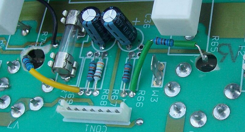
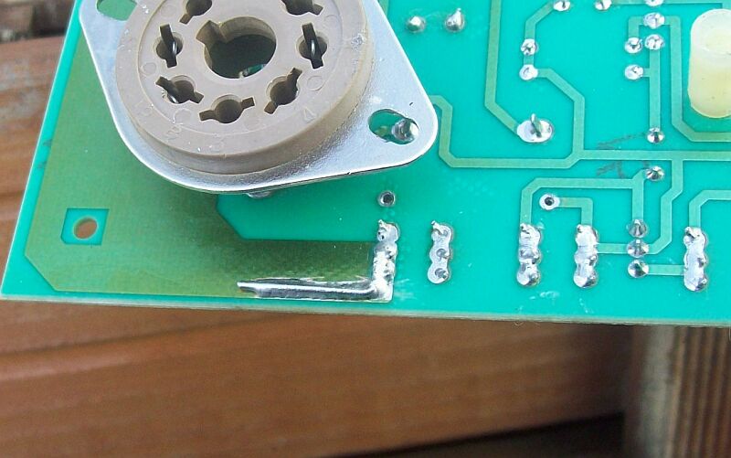
The following two pictures show what I did.
I scraped off a little bit of the green protective lacquer and soldered a little wire between the post and the copper-strip.
This prevents further damage to the motherboard and gives the tubes the "food" that they need.
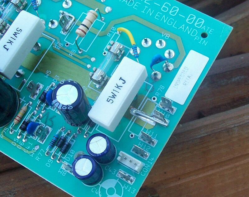
To do this job on the component side of the motherboard you need to desolder the 100 Ohms resistor R78. This resistor and the resistor R8 (also 100 Ohms) balance the heater-filaments to GND. I decided not to solder these resistors back into their former place. I soldered them to the sockets at tube V5 - as seen in the pic below.
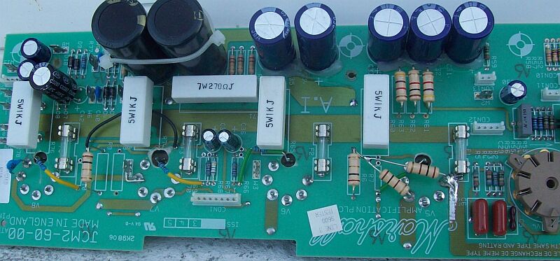
Finally - here is a pic of the complete repaired and modified motherboard. I reassembled the amp and gave it back to my friend Ralph. He uses this amp almost daily now - with a better sound (due to the 5k6 resistors mentioned) and without any thermal drift problems.
Keep rocking!
Fred
\\\ update: Spring 2013 ///
here's Glenn Martin's take on things ...!!
(*!*)
I've worked on a few of these monsters. The major issue you are missing (and I have missed for years) is not on the power amp board. It is on the overdrive channel front control Board. (dwg TL1--612-02.dgm). The capacitors in the circuit in the upper right hand of this drawing (C36 & 37) are connected via Con 20 to Con 12 on the power amp board and the right sides of resistors 4 and 5 on the power amp board. These capacitors are 100n at 63 volts. They invariably cannot handle the onrush voltage from V4, eventually becoming leaky and pull down the bias on the output tubes. This initiates all the troubles in these units. When these are replaced with 250 volt capacitors, the bias stabilizes under all temperature conditions, and
the unit will function as advertised (after all the major repairs in your article have been accomplished). ALSO. I replace C46 on the power amp board with a 9 inch length of open terminated RG58. This has about 25 pf of capacitance, but can handle the voltage and heat in this unit much better than that small capacitor.
... (ed. I think he means TL01_61_02.pdf)
Hi JC. Im just using the TSL 122 schematics found on the net. You'll notice that I referred to the Schematics by the drawing numbers found on the diagrams, and by their names. I dont know why , but I suspect that the problem isnt really solved by the mother board swap, and that most people just give up. There is No way the problem can be solved without replacing these capacitors. take a serious look and it will become apparent to you too. Its just Basic electronics. Once they begin to leak, they will draw down the bias on whatever tube pair they are connected to. Follow the instructions I gave you. I also change the minimum bias set resistor (R69 on drawing TL10-60-02). from 22k to 39 k. This increases the bias on the tubes and decreases the bias current. I set bias to 70ma per pair. Since R69 is now larger , as the internal temperature of th eamp increases, the resistance of this resistor increases positively IN GREATER PROPORTION TO THE OTHER RESISTORS IN THE BIAS NETWORK. This causes the bias to increase as the internal temperature increases, and the bias current to decrease slightly, a much safer situation. Try it and see.
Glenn Martin
Martek Mississippi Electronic Repair
Biloxi, MS
... thanks Glenn !!!
viva Analog /// jc -> lynx.net