MXR Phase45 Clone and Mods
All Mods Copyright (c) JC Maillet 2003, 2004
 |
Univibing the Phase45
I had never played a MXR Phase45 before - based on a friend's recommendation and reviews I decided to build one ... the Univibing mods are quite simple: a variable output mixer for dialing in pitch-shifting vibrato or Univibe-like Chorusing, the Univibe-sounding 10:1 cap ratio in the all-pass filters and a pulsing LED speed indicator ...
[NOTICE: that is not to say this ends up being a Univibe clone in any sense ... I'm just exporting some of the Univibe math to this two-stage platform to give it a cool sound, the Vibe is a four stager and sounds a lot thicker]
the external bias control came later after hearing the light/dark effect it had on the phasor, similar to the "offset control" mod on the bulb driver in my Univibe .... the 45 is a light sounding phaser, not too intrussive - it's awesome on a nice tube amp ...
Mods drawn over Justin Philpott's Schematic
Modded Phase45 ProtoClone Instructions (2004)
Overnite Sensation // Tour-Bus Version
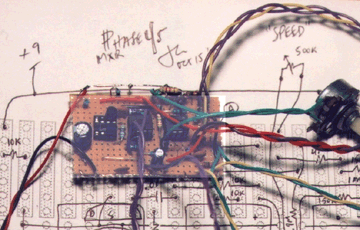
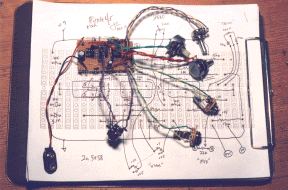
The bonus with strip-board is that usually you can have a pedal built totally from scratch in just a few hours - plus there's less pollution and mess involved ... study the schematic well before-hand, then check you've got all parts to make the circuit work - you should need no more than a dozen FETs to find two that are matched well enough to make this circuit work great (I used 2n5484's) ... first trace a plan of the circuit layout on a strip-board sheet - you should draw your own ... double check everything in the strip-layout two or three times against the schematic to make sure every connection is accounted for before moving to solder ...
Wire in a +9 and gnd rail on the outside of the strip-board and then solder in three 8-pin dip sockets, two will be used for op-amps and one for the two FET devices - which will need to be popped in and out later ... I use a magnifying glass after every solder to make sure there's no shorts anywhere ... once all the parts are populating the board and I've given it a good look over against the original schematic I attach wires at all wire points and then wire in the pots and jacks ... it's easier to test and debug the circuit outside of the box wired without a footswitch first - so you'll need to wire a ground wire from the gdn bus to both input and output jacks ... hook up a battery clip to the rails and stick one side of the battery in the clip, then use your multimeter and short out the remaining battery clip terminal and other battery terminal to meausre the current flow going through the circuit and battery - it should lie in the low mA range if you haven't shorted out anything ... do the same thing with the two op-amps plugged in, still should have a low mA reading ...
 |
Matching FETs for the Phase45
the FETs operate under zero Drain-Source bias conditions (ie zero DC current through the device) and so it is improper to speak of device gain in this application ... rather we want to match FET-Channel Resistance dependence to Vgs voltage - this involves more than Threshold voltage matching ... the best technique is likely testing devices out individually "in circuit" against bias sweeping ...
Take out your batch of FETs, plug one transistor at a time in any of the two FET locations (it doesn't matter which) and sweep the bias trimpot and see if you can "bias-in" that device and have the circuit phase along with the LFO ... ** some device will seem to happen just as the trimpot sweep hits one extreme - discard those devices or the ones where nothing happens at all, keep the ones where the device wakes up somewhere near the middle of the bias sweep ** ... note that in testing the phasor with only one FET the circuit is operating on a half-phase basis - still sufficient for testing out devices response to bias sweep ... from the subset of those devices that exhibit somewhat centered bias "peaking" choose two that seem to wake up around the same spot in the trimpot's sweep and have an overall similar response to bias sweeping, these will be two-way matched for our needs ... stick those two devices in the circuit and set the bias to the middle of the peak response region - on my pedal the bias control is externally controllable because, as you'll notice, the bias sets the "average" brightness of the filter and it provides different shades of the effect ...
 |
Good luck !!
viva Analog /// jc CHEZ lynx.net


